


How to connect them properly?
[accordion]
[toggle title=“1.1. General information – Why differential outputs?“]
 CSMIO/IP devices were designed to be maximally reliable and resistant to interference. In industrial environment electromagnetic interferences is often on a very high level. Signals which control the motion of the axes – STEP/DIR are the most exposed to influence of interference because these are very fast signals, especially in CSMIO/IP-S controller – up to 4MHz.
Professional motors controllers (both servo and stepper) have STEP/DIR inputs properly prepared to connect them in way that is resistant to outside interferences. This is done by so-called differential signals, which are incomparably higher resistant to interference.
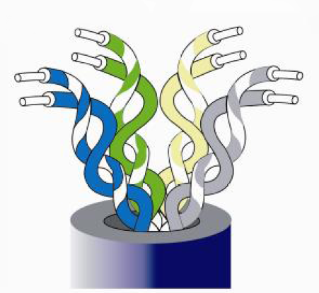
Differential connection is made with twisted pair of cables what means that every signal needs two cables – positive (+) and negative (-). It has nothing in common with power, so e.g. (-) signals cannot be connected with GND of the device because this way the device will be damaged!
Someone can say that we have just mentioned reliability and now the threat of damage. As it happens in life – something for something. Fast differential outputs can be protected like regular, other I/O signals. Differential line must have standard parameters, which would change if there were additional protection components used. On the other hand, if we use regular outputs, then the connection of many professional drives would be almost impossible. Some drives have optically isolated inputs with so-called optocouplers – in this case, both regular and differential signals can be connected. However, many drives have so-called differential line receivers on the fast inputs and then a regular signal connected will cause impulses dropping and positioning errors.
In summary, differential outputs are the option that is the most resistant to interference. It is also the most universal solution but attention should be paid while connecting because it is easily to damage these outputs if we will do it the wrong way.
[/toggle]
[toggle title=“1.2. Signs used in this guide“]
![]() Such a connection will not cause damage and will work properly.
Such a connection will not cause damage and will work properly.
![]() Such a connection will not cause damage but it will not work properly.
Such a connection will not cause damage but it will not work properly.
![]() Such a connection will cause CSMIO/IP hardware damage.
Such a connection will cause CSMIO/IP hardware damage.
[/toggle]
[toggle title=“2.1. Motors drivers with optocoupler input“]
Optocoupler input is the best available option in terms of resistance to interference and convenience of connection. For each signal, twisted pair of cables is needed. Of course connecting larger number of axes you can use cables, which have more pairs – e.g. computer network cable has 4 pars, so you can connect STEP+/STEP- signals and DIR+/DIR- for two axes.
If motor driver has optocoupler inputs then there is no need to connect GND of the devices too.
[/toggle]
[toggle title=“2.1.1. Proper connection to optocoupler inputs“]

Signs on the drive may differ so you should first read the documentation carefully. It can be e.g. PUL+/PUL- and SIGN+/SIGN-, however it is not a rule. Servo drives often have two different types of STEP/DIR inputs. However usually (not differential) to work on low frequency and the second for high frequencies. We always use differential inputs for high frequencies even if we work with slower CSMIO/IP-M.
[/toggle]
[toggle title=“2.1.2. Proper connection to optocoupler inputs with shared cable“]
This variant is a little bit worse because of lower interference resistance and it is a bit more difficult to connect.

In this case, we do not use twisted cable and that is why the connection is more exposed to the influence of interferences. Shared cable (cathode) is connected to the GND of the device, in the CSMIO/IP-S it is 13th PIN of STEP/DIR connector, and in the CSMIO/IP-M we have to use the GND on 2nd PIN or ANALOG I/O 8 connector because there is no GND PIN on STEP/DIR connector.
![]() It is important to do not connect STEP- and DIR- pins with GND of the device because it will cause short circuit and output stages damage.
It is important to do not connect STEP- and DIR- pins with GND of the device because it will cause short circuit and output stages damage.
[/toggle]
[toggle title=“2.1.3. Incorrect connection to optocoupler inputs sample“]

![]() Because of short circuit between STEP- and DIR- signals in such a connection The CSMIO/IP controller will be damaged. Warranty does not cover damages caused by incorrect connection!
Because of short circuit between STEP- and DIR- signals in such a connection The CSMIO/IP controller will be damaged. Warranty does not cover damages caused by incorrect connection!
[/toggle]
[toggle title=“2.2. Motors drives with differential line receiver“]
It is very often used solution because line receivers are less expensive than fast optocouplers and that is why drives manufacturers prefer them.
However, reliability of this solution is on a very high level, the difference in relation to optocouplers is necessity of additional GND of the devices connection, and shielding needed even for short connections.
[/toggle]
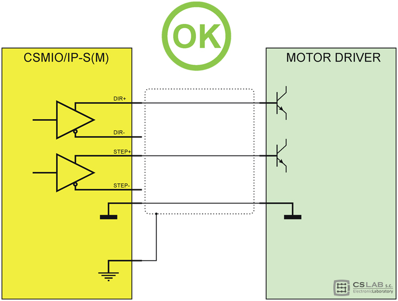
[toggle title=“2.2.1. Sample of proper connection of the inputs and differential line receiver“]
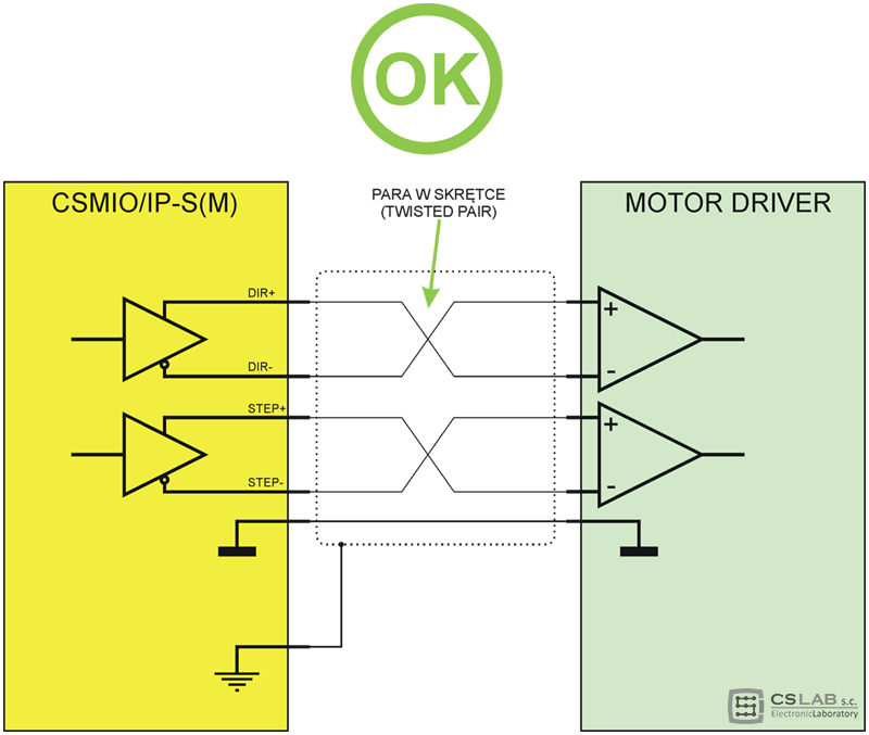
As you can see in the scheme above the connection is very easy. This example applies to single drive but the others we connect the same way and do not forget to connect GND to all the drives.
The shield is available on cover of the connector in CSMIO/IP-S(M). Shielding should be connected only from the side of the CSMIO/IP controller.
GND in the CSMIO/IP-S is on 13th PIN of STEP/DIR connector, in the CSMIO/IP-M we have to use the GND on 2nd PIN or ANALOG I/O 8 connector because there is no GND PIN on STEP/DIR connector.
[/toggle]
[toggle title=“2.2.2. Incorrect – lack of devices GND connection“]

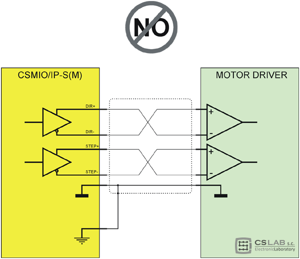
![]() Such a connection will not cause any damage but it will not work properly. Moreover, work results can be weird as positioning errors that will show up and hide next minute. The GND of devices must be connected even if all seems to work fine without it.
Such a connection will not cause any damage but it will not work properly. Moreover, work results can be weird as positioning errors that will show up and hide next minute. The GND of devices must be connected even if all seems to work fine without it.
[/toggle]
[toggle title=“2.2.3. Incorrect – GND and shielding connection“]
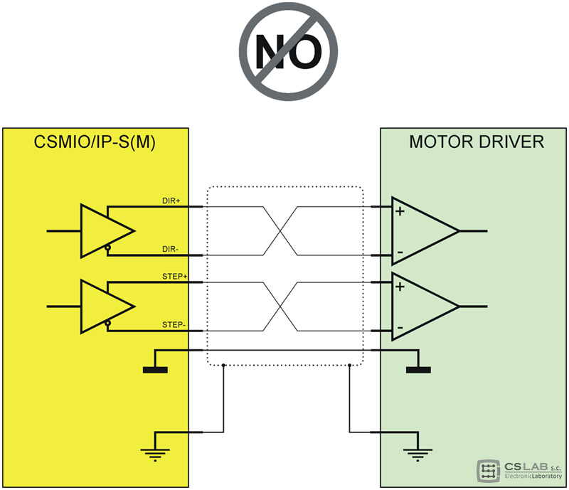
![]() Such a mistake can also be unnoticed for a long time. In some cases, it does not cause any visible problems. However GND and shielding should not be connected. Negative effects in this case can be noticeable from time to time, then it is hard to find it if we do not know the reason.
Such a mistake can also be unnoticed for a long time. In some cases, it does not cause any visible problems. However GND and shielding should not be connected. Negative effects in this case can be noticeable from time to time, then it is hard to find it if we do not know the reason.
[/toggle]
[toggle title=“2.2.4. Incorrect – both-sides shielding connection (loop)“]
![]() This quite common mistake appears during installation and usually does not cause visible, negative results (especially with short cables). However, this connection is a mistake, which can show up in some specific situations.
This quite common mistake appears during installation and usually does not cause visible, negative results (especially with short cables). However, this connection is a mistake, which can show up in some specific situations.
[/toggle]
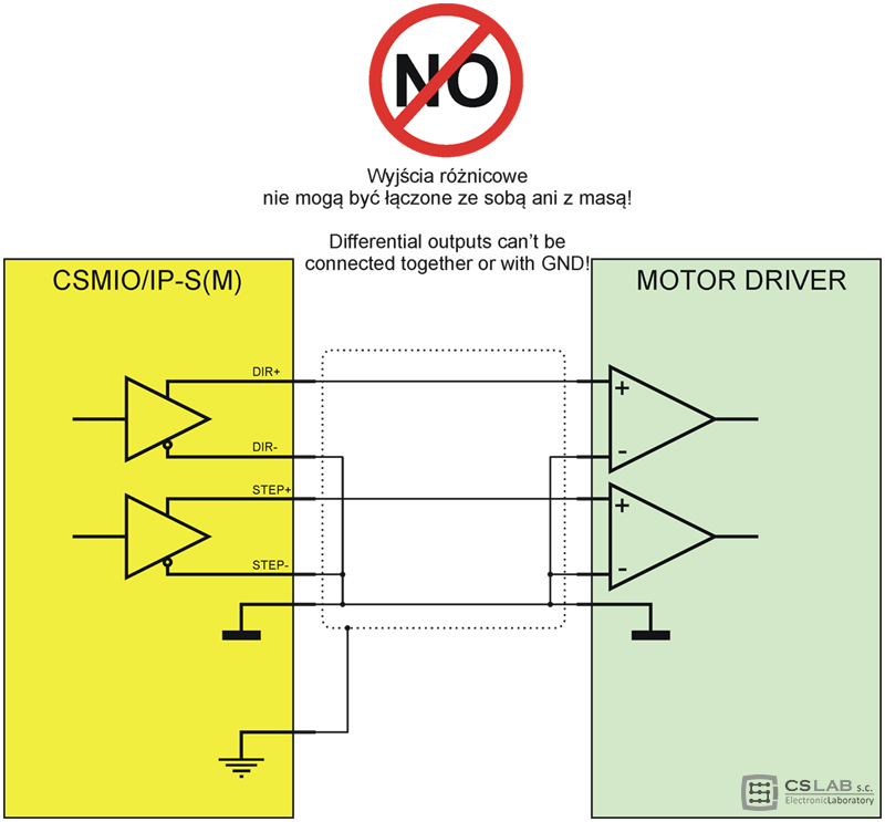
[toggle title=“2.2.5. Incorrect – connection of STEP- and DIR- signals“]
![]() This connection causes CSMIO/IP hardware damage! Warranty does not cover damages caused by incorrect connection!
This connection causes CSMIO/IP hardware damage! Warranty does not cover damages caused by incorrect connection!
The DIR- and STEP- signals are not the GND and you cannot connect it together. It causes short circuit and damage of the output stage in the CSMIO/IP device.
[/toggle]
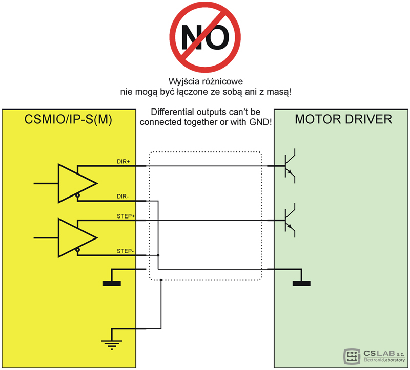
[toggle title=“2.2.6. Incorrect – connection of the STEP- and DIR- signals to the GND“]
![]() This connection causes CSMIO/IP hardware damage! Warranty does not cover damages caused by incorrect connection!
This connection causes CSMIO/IP hardware damage! Warranty does not cover damages caused by incorrect connection!
The DIR- and STEP- signals are not the GND and you cannot connect them together. It causes short circuit and damage of the output stage in the CSMIO/IP device.
[/toggle]
[toggle title=“2.3. Connection to transistor inputs“]
Transistor-type inputs are less common. It is not the best solution because of quite low resistance to interferences and lack of galvanic isolation. This type of STEP/DIR inputs is intended for low frequencies, of about 250kHz.
![]() You should pay attention to used voltage standard because sometimes happens that this type inputs are in 24V standard. Differential outputs of the CSMIO devices work in 5V standard so the connection will not be possible. Read documentation of the drive carefully.
You should pay attention to used voltage standard because sometimes happens that this type inputs are in 24V standard. Differential outputs of the CSMIO devices work in 5V standard so the connection will not be possible. Read documentation of the drive carefully.
[/toggle]
[toggle title=“2.3.1. Example of correct connection to the transistor inputs“]
While connecting the CSMIO/IP to the transistor inputs remember to connect the GND and to left the STEP- and DIR- outputs unconnected. Shielding is very important.
GND in the CSMIO/IP-S is on 13th PIN of STEP/DIR connector, in the CSMIO/IP-M we have to use the GND on 2nd PIN or ANALOG I/O 8 connector because there is no GND PIN on STEP/DIR connector.
[/toggle]
[toggle title=“2.3.2. Incorrect – short circuit of STEP- and DIR- signals and if were taken instead of GND“]
![]() This connection causes CSMIO/IP hardware damage! Warranty does not cover damages caused by incorrect connection!
This connection causes CSMIO/IP hardware damage! Warranty does not cover damages caused by incorrect connection!
The DIR- and STEP- signals are not the GND and you cannot connect it together. It causes short circuit and damage of the output stage in the CSMIO/IP device.
[/toggle]
[toggle title=“2.3.3. Incorrect – short circuit of STEP-, DIR- signals and GND“]

![]() This connection causes CSMIO/IP hardware damage! Warranty does not cover damages caused by incorrect connection!
This connection causes CSMIO/IP hardware damage! Warranty does not cover damages caused by incorrect connection!
The DIR- and STEP- signals are not the GND and you cannot connect it together. It causes short circuit and damage of the output stage in the CSMIO/IP device.
[/toggle]
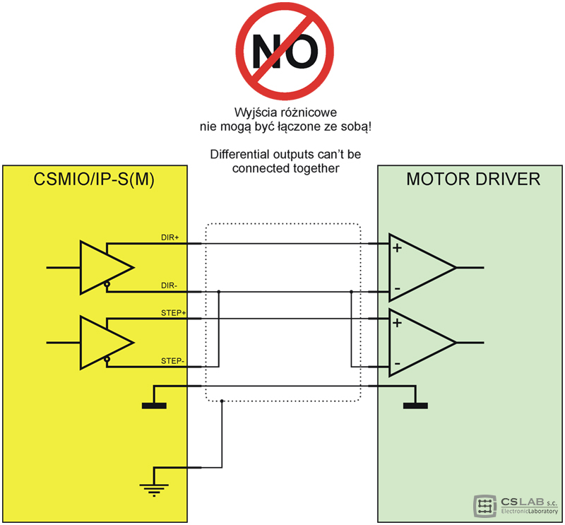
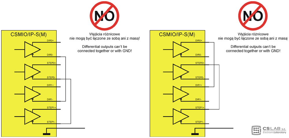
[toggle title=“2.4. Common mistake while connecting drives for several axes“]
„-” and „+” signs placed next to the STEP/DIR signals labels do not imply neither power nor anything like that. These signals cannot be connected together in no case because it will cause damage of the outputs stage of the CSMIO/IP controller.
In the scheme below there were shown incorrect connections that cause failure of any device with differential line transmitter which are also CSMIO/IP-S and M.
While users connect “plus” signals relatively rare, they connect “minus” signals quite often as they confuse them with the GND of the device.
[/toggle]
[toggle title=“3. Summary – short author’s note“]
Making an installation of a complete control system for CNC machine we very often connect with each other components that have a high value. That is why it is worth to spend some time to analyze the documentation of the devices that we are going to use. While many installations and launching for my clients I have made more than one expensive mistake myself. To exclude situation like that you should avoid the rush and do your work as carefully as possible.
You should remember that any electronic device is not fully resistant to incorrect installation. Some mistakes only cause that the whole system will not work properly, some of them unfortunately will cause damage of one or more components. Details are most important in these type systems. Not so long ago I even thought by myself that things like the way of shielding connection or grounding should have no bad influence on how CNC machine control system work. The practice shows something else. Every detail matters if we want our control system to work perfectly and reliably. Users that have less experience should particularly spend more time with the documentation of ale the devices they will use. In addition, Internet is valuable source of useful information, however you should be careful of what source you are going to use because – especial on forums there is many unprofessional advices.
[/toggle]
[/accordion]
